![]()
![]()
![]()
![]()
Boat Design and Fairing Example
This section describes the process of creating, shaping and fairing a round bilge hull form. It discusses surface shaping and fairing techniques as applied to a 3D boat hull.
Please review the previous section of this tutorial on Shaping and Fairing Surfaces before you begin this section of the tutorial. Many of the concepts discussed there are applied here without elaboration.
![]() Start the
ProBasic/ProSurf program
Start the
ProBasic/ProSurf program
![]() Open or resize a new
window
Open or resize a new
window
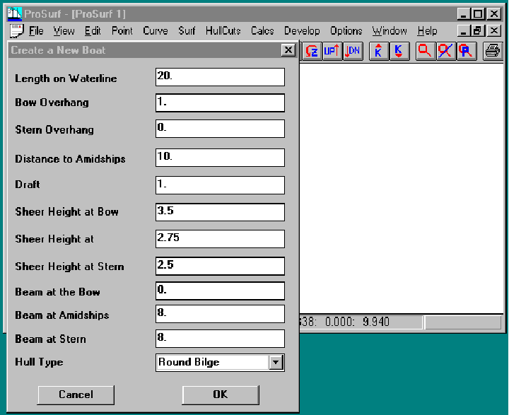
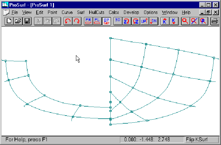
Start by creating a new boat based on the principal dimensions shown above.
![]() Select the File-Create
Boat dialog box
Select the File-Create
Boat dialog box
![]() Set the bow overhang to
1.0
Set the bow overhang to
1.0
![]() set the hull shape to
"round bilge"
set the hull shape to
"round bilge"
![]() Leave the rest of the
principal dimensions alone
Leave the rest of the
principal dimensions alone
![]() Press the OK button
Press the OK button
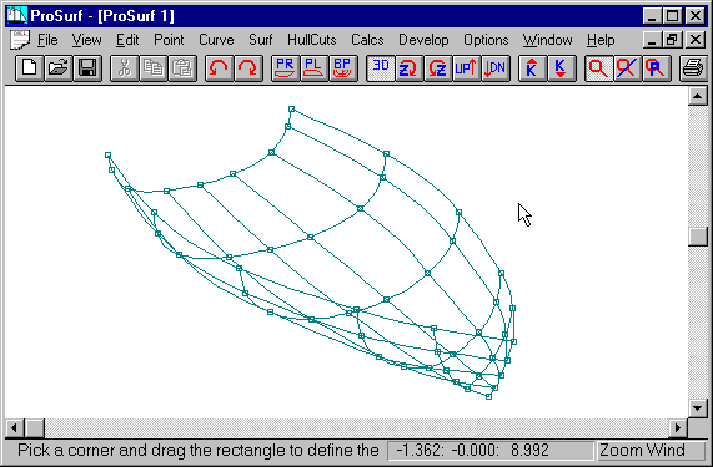
The following four pictures show the boat that results from this Create Boat command. No changes have been made to the boat.
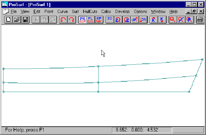
Profile view of the created boat.
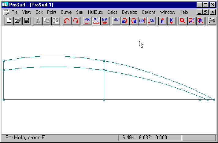
Plan view of the created boat.
![]() Select the Plan view
Select the Plan view
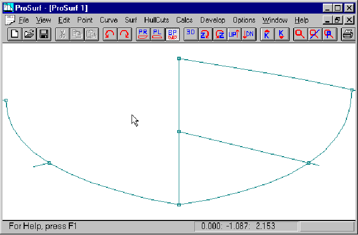
Section view of the created boat.
![]() Select the Section view
Select the Section view
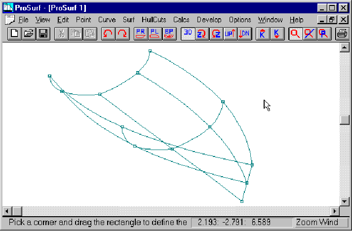
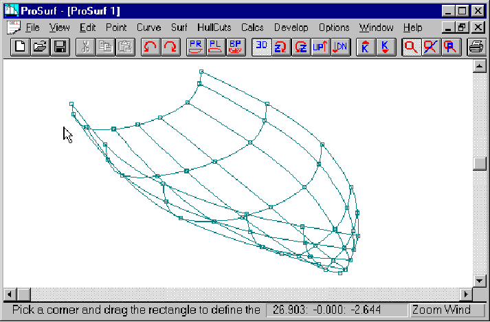
3D view of the created boat
![]() Select the 3D view
Select the 3D view
![]() Rotate the boat using
the Z-rotate buttons and the Up/Down buttons
Rotate the boat using
the Z-rotate buttons and the Up/Down buttons
This is the starting hull shape to create a round-bilge hull.
The overall shaping and fairing process can be summarized like this:
1. Create the hull with the Create Boat command.
2. Add more shape control by adding in a row and/or a column.
3. Rough-shape the hull by eye using the Move Point command
4. Repeat steps 2 and 3 until you feel that you have enough rows and columns to define the hull.
5. Begin the detailed fairing process using the k-curves and the Move% command.
6. Fair the surface rows in the profile view.
7. Fair the rows in the plan view.
8. Fair the columns in the section view.
9. Repeat steps 6, 7, and 8 until the boat is fair.
10. Verify the fairness by displaying the lines drawing or the Gaussian curvature display.
(As noted before, we will refer to the longitudinal surface lines as rows and the vertical or transverse surface lines as columns. This may not actually be the case internally, but this assumption makes it easier to describe the shaping and fairing techniques.)
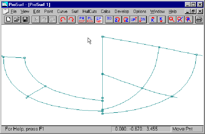
Since the hull is currently only defined by 3 rows and 3 columns, there is not much that can be done for rough shaping of the boat at this time, so we need to start adding rows and/or columns to give us more control points. As discussed elsewhere, NURB surfaces are defined by a rectangular grid of rows and columns. Although these rows and columns can be oriented any way you choose, there are some rules you should follow. (Many of these rules are discussed in the previous section of the tutorial.) The most important one is to add the rows and columns evenly over the length of the surface. This will ease the hull shaping and fairing process.
As you already know by now, the defining NURB surface rows and columns are not necessarily waterlines, buttocks, stations, or diagonals. This is the biggest change in going from designing on the drafting board to designing on the computer. You shape and fair a hull using these rows and columns, rather than shaping and fairing the traditional lines of the boat. In the program you can, however, have the program automatically "cut" and draw any traditional waterline, buttock, station, etc. so that you can see how they change shape when you move one of the NURB surface points. (See the paper on Hull Design: From the Drawing Board to the Computer, by Stephen M. Hollister.)
Although the columns of the hull surface are close to being stations, there is no absolute requirement that the columns remain in one transverse plane. They are allowed to wander back and forth and any which way. We have found that if we force many of the columns to remain fixed to one transverse plane (like a station), then it is easier to define and fair the hull in section view. You can't fix all of the columns, because the typical bow and stern (which are two of the columns of the surface) are angled over and are not stations. In addition, you also need to have some transition columns to try and maintain an even spread of columns along the length of the hull.
In the middle of the hull, we like to add in columns as "Vertical Fixed", which means that once the column has been added to the surface, it cannot be moved in the longitudinal X-direction. You can unfix the column at some later time, if necessary. As you will see, there are three ways to add in rows and columns:
1. Angle - which means that there is no restriction to its position - Add Row/Col Angle
2. Vertically Fixed - which means that the row/column cannot be moved from that plane - Add Row/Col VertFix
3. Horizontally Fixed - which means that the row/column cannot be moved from that plane - Add Row/Col HorzFix
The meaning of vertical and horizontal depends on the view you are using to add the row or column. Generally, columns are added in profile or plan view and are fixed vertically. Horizontal fixing is much less useful, but is available, if necessary.
We will start by adding in a couple of columns to the boat.
![]() Display the profile
view of the boat
Display the profile
view of the boat
![]() Select the Add Row/Col
- Add Row/Col VertFix command
Select the Add Row/Col
- Add Row/Col VertFix command
![]() Add the columns in at
the locations shown in the picture above. Note that the new
columns were added in roughly one-half way between two existing
columns.
Add the columns in at
the locations shown in the picture above. Note that the new
columns were added in roughly one-half way between two existing
columns.
![]() Display the different
views to evaluate the new boat shape
Display the different
views to evaluate the new boat shape
The Body Plan view may show a split-up column located at amidships. This happens when the program "flips" the stations from the right side of the centerline to the left side of the centerline. If one of the columns is located at exactly the "flip" point, then the column may get split up. See the dialog box below to see how this is solved.
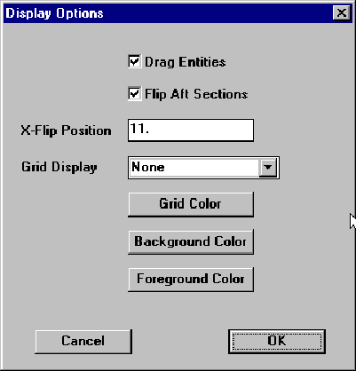
You can change the "flip" location where the program splits the forward and aft hull shape in Body Plan view. All parts of the hull with x-values less than this X-flip position will be drawn on the right of the centerline and all parts of the hull with x-values greater than this X-flip position will be drawn on the left. Select the Options-Display Options dialog box and change the value for the X-flip position.
![]() Select the
Options-Display Options menu choice
Select the
Options-Display Options menu choice
![]() Change the value in the
X-Flip Position field from 10.0 to 11.0
Change the value in the
X-Flip Position field from 10.0 to 11.0
![]() Pick the OK key
Pick the OK key
You will now see that the flip position has changed in the Body Plan view.
Now that two new columns have been added to the hull, you need to do some rough shaping of the hull in all three views using the Move Point command. We will wait a while before performing some detailed fairing.
![]() Select the Move Point
command
Select the Move Point
command
![]() Rough shape the hull in
all three views given the current number of rows and columns
Rough shape the hull in
all three views given the current number of rows and columns
![]() You may have to cycle
through each view several times to get the shape you want
You may have to cycle
through each view several times to get the shape you want
![]() Try and keep the rows
and columns evenly spread
Try and keep the rows
and columns evenly spread
Remember that the general process is to add a few rows and columns and then to perform some rough shaping of the hull in all views. This is a better approach than trying to add all of the rows and columns before attempting any kind of hull shaping.
The following view shows what the hull might look like after your rough shaping process.

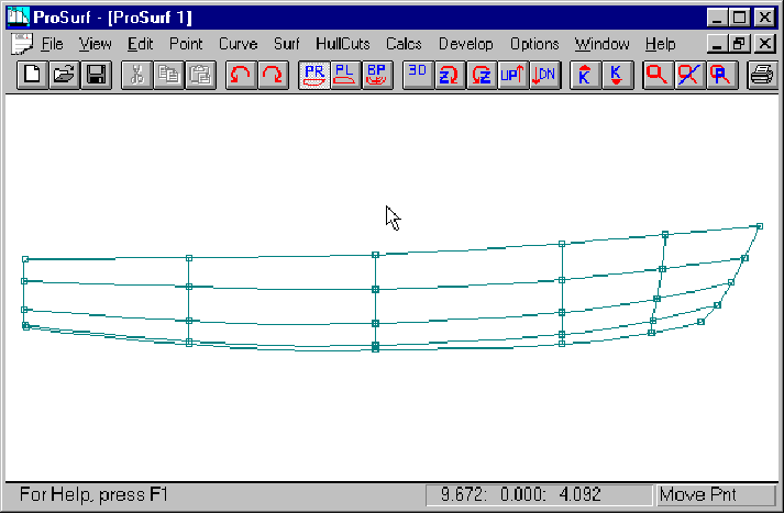
This is the profile view after the initial rough shaping process.
This is the plan view after the initial rough shaping process.
This is the section view after the initial rough shaping process.
This is the 3D view after the initial rough shaping process.
Now that you have roughed up the shape a little bit, you may wish to evaluate the lines of the boat: stations , waterlines, and buttocks. This process is explained below.
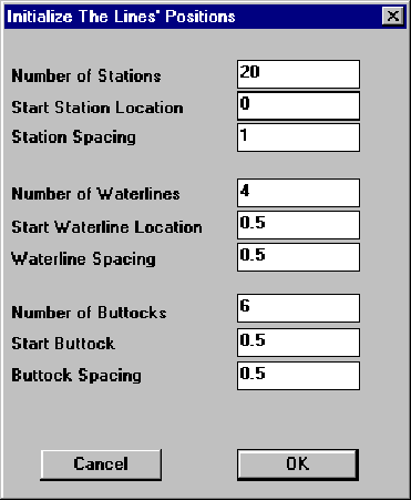
This is the "hullcuts" initialization dialog box. ProBasic and ProSurf refer to any planar cut of the NURB hull surface as a hullcut. Standard hullcuts are stations, waterlines, buttocks, and diagonals. In fact, you can define any angled planar cut of the surface. The goal of this dialog box is to define an initial set of lines to use to cut the hull surface. These lines are also used in the lines drawing view (see the View-Lines Drawing command) and the stations that are defined here are used for the hydrostatic calculations. This hullcuts definition is done only once to give you an initial set of lines. Afterwards, you can add, modify, or delete any of these lines.
To create an initial set of hullcut lines, you need to follow these steps:
![]() View the hull in all
three views to determine an appropriate set of stations,
waterlines, and buttocks
View the hull in all
three views to determine an appropriate set of stations,
waterlines, and buttocks
![]() Select the
Hullcuts-Initialize Hullcuts command
Select the
Hullcuts-Initialize Hullcuts command
![]() For this hull example,
set the values to those shown in the picture above
For this hull example,
set the values to those shown in the picture above
![]() Select the OK button
(you won't see any changes at this time)
Select the OK button
(you won't see any changes at this time)
![]() To see the lines of the
hull, select the Hullcuts-Display Lines-Display All Lines command
To see the lines of the
hull, select the Hullcuts-Display Lines-Display All Lines command
The buttocks will be drawn in the profile view. The waterlines will be drawn in the plan view. The stations will be drawn in the body plan view.
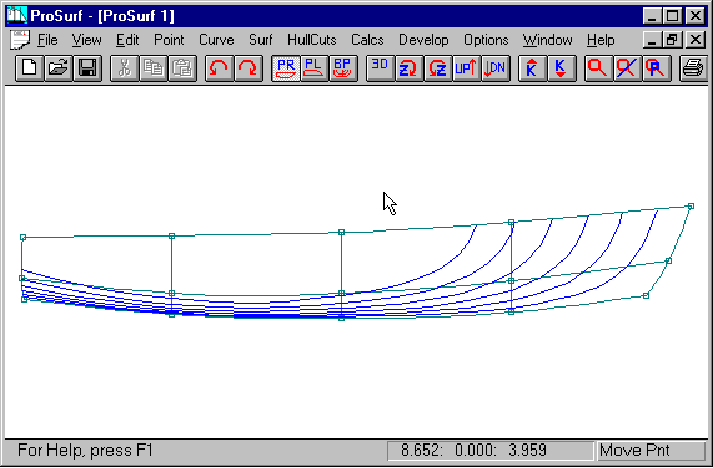
This picture shows the profile view with all buttocks automatically cut and drawn. You can, if you have a fast enough computer, use the Move Point command and watch the buttocks get dynamically recut and drawn while you drag the hull point. (If you select only one or two hullcuts at a time, then this dynamic dragging of the hull and recutting of the hullcuts works much faster.) This will work for any lines in any view. This can be useful to see how changes in any of the defining points affect the lines of the boat. You can also use this technique for fairing with the k-curves turned on and using the Move% command. You can leave the hullcuts turned on or you can turn them off at any time.
![]() Turn off the lines by
selecting the Hullcuts-Display Lines-Turn Off All Lines command
Turn off the lines by
selecting the Hullcuts-Display Lines-Turn Off All Lines command
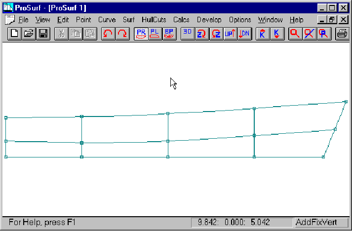
Now that we have added two columns and performed the rough fairing of the hull, we will proceed to define more rows and columns and continue with the rough shaping process.
After viewing the hull in all views, we really need another column up near the bow to help define that area better. Since we want the columns to be spread over the surface evenly, we shouldn't add the column in as a vertically-fixed column. We need to make a transition from the vertical columns in the middle of the boat to the angled over column at the bow. This is done with the Surf-Add Row/Col-Add Row/Col Angle command. "Angle" means that the program will insert the column proportionally in the area that you pick, as shown in the picture above. Note that the column is angled roughly one-half way between the vertical column to the left and the bow column.
![]() Select the Surf-Add
Row/Col-Add Row/Col Angle command
Select the Surf-Add
Row/Col-Add Row/Col Angle command
![]() Position the cursor
along one of the rows roughly one-half way between the bow and
the first vertical column and "pick" the left mouse
button
Position the cursor
along one of the rows roughly one-half way between the bow and
the first vertical column and "pick" the left mouse
button
The program will insert the angled column into the hull. Since this column is not vertically fixed, you can position the points anywhere you wish.
Also note that we are still satisfying the recommended 2:1 rule which says that if you have two rows or columns which are 1 foot apart, then the next row or column should be no more than 2 feet further away. You will always meet this rule if you add new rows or columns one-half way between two existing rows or columns.
We also want to add in two more rows to better control the shape of the sections. This can best be done in Body Plan view.
![]() Select the Body Plan
view
Select the Body Plan
view
![]() Select the Surf-Add
Row/Col-Add Row/Col Angle command
Select the Surf-Add
Row/Col-Add Row/Col Angle command
![]() Add two rows into the
hull by splitting the distance between the three existing rows,
as shown in the picture above
Add two rows into the
hull by splitting the distance between the three existing rows,
as shown in the picture above
The added rows will slightly change the shape of the hull, since we are using the points on the surface. The Add Row/Col Angle command was used because these rows will not be planar like a diagonal. They need to be able to flow along the length of the hull. It is best if you think of the rows as iso-girth lines, equally spaced along each of the columns. Note that the spacing does not HAVE to be equal. It is best, however, if you keep the spacing within the 2:1 spacing maximum.
Now that we have added in some more rows and columns, you need to repeat the rough shaping process in all views using the Move Point command. Resist the urge to start fairing yet using the k-curves and the Move% command. Wait until you get the shape a little bit closer.
![]() Rough shape the hull in
all views using the Move Point command
Rough shape the hull in
all views using the Move Point command
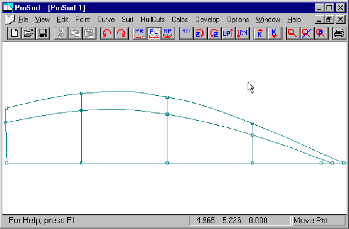
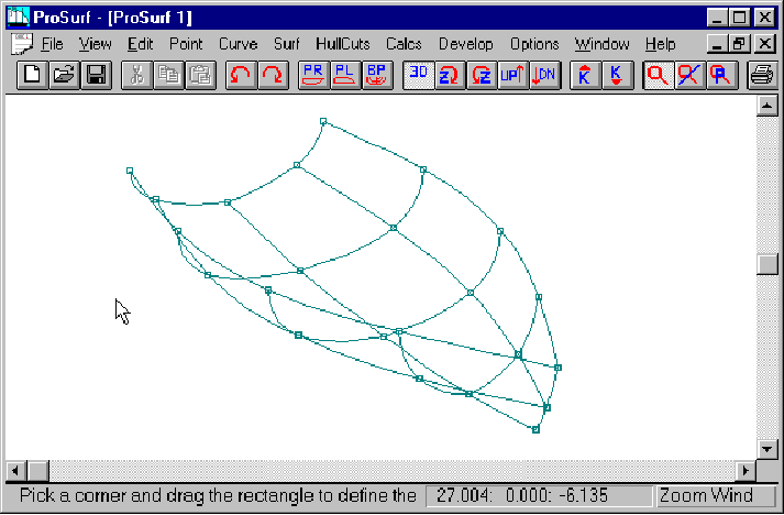
The results of this rough shaping are shown below.
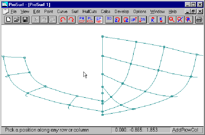
This is the profile view after the latest series of rough shaping moves.

This is the plan view after the latest series of rough shaping moves.
This is the section view after the latest series of rough shaping moves.
This is the 3D view after the latest series of rough shaping moves.
This is the overlay lines view (see the View-Lines Drawing command) of the hull.
Now that the rough shaping is complete, the fairing can be done using the Move% command and the k-curves. You must review the previous section of this tutorial first, since this discussion assumes you understand that material.
A detailed fairing process is performed as follows:
(You may develop your own variation.)
1. Select the Profile view of the boat.
Turn on the k-curve of the top row (sheer)
Fair the sheer with the Move% command
Turn on the k-curve for the bottom profile
Fair the bottom profile
Use the k-curves to fair the intermediate rows
Fairness of the intermediate rows is not as critical as the fairness of the sheer and profile
2. Select the Plan view of the boat
Turn on the k-curve of the top row (sheer)
Fair the sheer with the Move% command
Use the k-curves to fair the intermediate rows
Fairness of the intermediate rows is not as critical as the fairness of the sheer
Adjust the angled column near the bow so it doesn't wiggle - don't fair it in this view
3. Select the Body Plan view of the boat
Fair the columns, one by one - some start with the amidships column and work towards the ends
Leave on multiple column k-curves to evaluate longitudinal shape changes
K-curves of consecutive columns should have comparable shapes
Smooth the shapes of the rows, but don't worry about detailed fairing of the rows in this view
![]() Steps 1, 2, and 3
should be repeated until fairness is achieved (within building
tolerances).
Steps 1, 2, and 3
should be repeated until fairness is achieved (within building
tolerances).
![]() Fair the rows in
profile and plan views and fair the columns in section view.
Fair the rows in
profile and plan views and fair the columns in section view.
![]() A good, even spread of
the rows and columns will greatly help the fairing process.
A good, even spread of
the rows and columns will greatly help the fairing process.
![]() Use the K-Up and K-Dn
buttons to adjust the curvature magnitude as necessary.
Use the K-Up and K-Dn
buttons to adjust the curvature magnitude as necessary.
![]() Turn on selected hull
cuts as needed.
Turn on selected hull
cuts as needed.
Waterlines are the most difficult to fair, especially near the bow and for the low waterlines. The reason for this is that their shape depends almost equally on the shape of the rows and columns. Since you cannot shape the waterlines directly, you have to do so using only the row and column points. The best approach to this problem is to selectively turn on one or two waterline hullcuts so that you can dynamically see how they change shape when you move one of the defining points (in plan view).
Low or shallow waterlines are also a problem because a very small (less than the building tolerance) change in the section (column) shape can have a dramatic effect on the waterline shape. Since the waterlines are automatically cut and drawn, you cannot fair their shape directly. Most hand-drawn lines drawings either avoided these shallow waterlines or "fudged" their shape to make them look good. For hand drafting, you could make the lines look fair, even though the lines did not match up exactly. With this computer program, everything is guaranteed to match up exactly, so this low waterline shape sensitivity is clearly obvious. The point to keep in mind, however, is that you only need to fair the boat to within building tolerances. If you find that when you use the Move% command you are moving points by less than the building tolerance (see the status line for this distance while you are dragging a point), then you are close enough for building purposes. Do not worry if the low waterlines don't look exact, it won't matter. Remember that many hand lines drawings had good looking waterlines that were incorrect.
![]() Follow the steps
discussed above to fair the hull
Follow the steps
discussed above to fair the hull
![]() You can use your own
variation of the process
You can use your own
variation of the process
When the fairing has been completed, the boat may will look something like the pictures below. Actually, this hull still needs to be fixed up a little in the forward ends of the waterlines. In addition, you will see that there is still one area that needs to be examined.
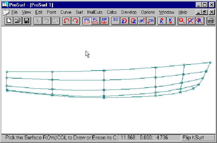
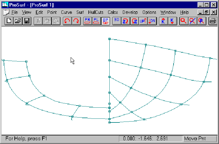
The faired profile view of the hull.
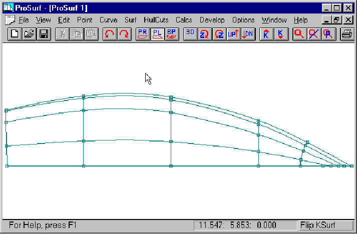
The faired plan view of the hull.
The faired section view of the boat.
The faired 3D view of the boat.
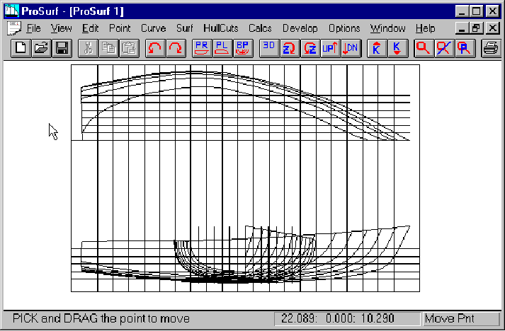
The overlay lines drawing of the boat.
There is another way to check the fairness of the boat using a curvature color display on the hull. It kind of looks like a finite-element stress map of the hull. The k-curves work best for detailed fairing, and this technique works best for overall surface evaluation.
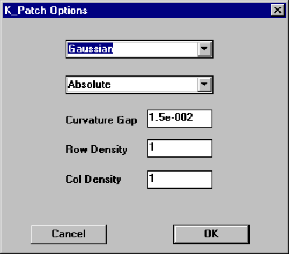
This dialog box allows you to set the parameters of the display of either Gaussian or mean surface curvature display. (See the Reference manual for a more complete discussion of this topic.) To get a full color display, we will change a couple of fields before continuing.
![]() Select the
Surf-K_Pat-K_Pat Options command to see this dialog box
Select the
Surf-K_Pat-K_Pat Options command to see this dialog box
![]() Change the fields with
the number 3 to the number 1 (as shown above)
Change the fields with
the number 3 to the number 1 (as shown above)
![]() Select the OK button
Select the OK button
This only changes the curvature settings and does not draw anything. To turn on the Gaussian curvature display, follow these directions:
![]() Select the Profile view
of the boat
Select the Profile view
of the boat
![]() Select the
Surf-K_Pat-K_Pat All command
Select the
Surf-K_Pat-K_Pat All command
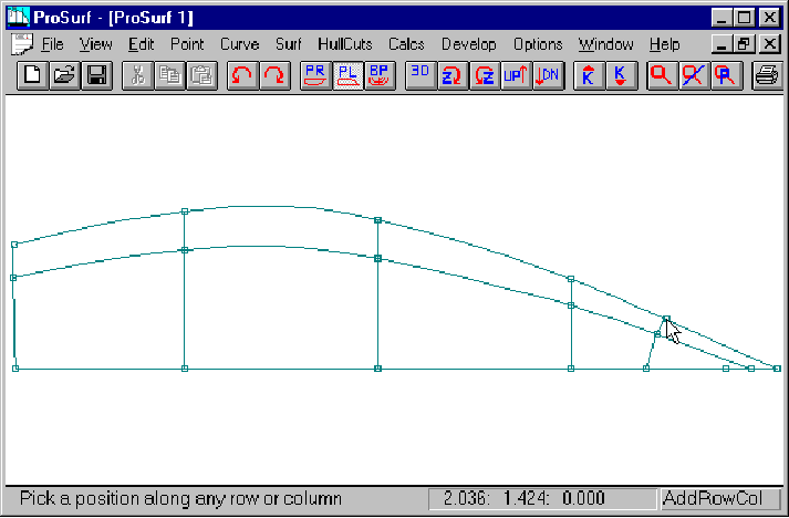
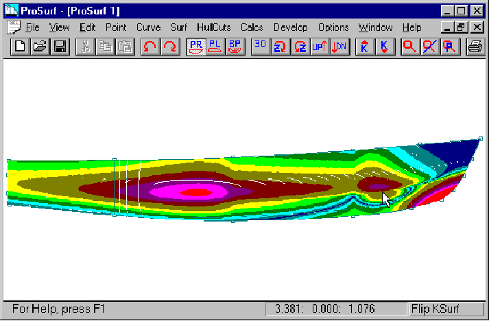
You should now see something like what is shown above. The hotter, redder colors indicate sections of the hull which have the greatest twist or double curvature, and the cooler, dark blue colors indicate areas where the hull is curved in only one direction. (Dark blue indicates a Gaussian curvature of zero and that means that the hull is developable in that area. See the Command Reference manual and the tutorial on developable hulls for further details.) What is important for fairing, however, is not the colors, but the smoothness in the shape and changes of the colors. Look at the colors in the area where the cursor is in the above picture. Note that the colors do not smoothly change shape in that area. This indicates a subtle unfairness in the shape of the hull.
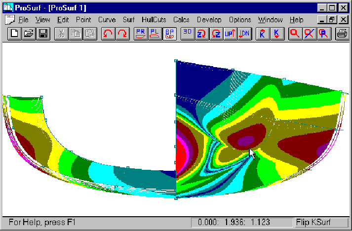
This is a section view of the same area showing the unfair color changes. This means that you should recheck that area using the k-curves. Be careful, because the Gaussian curvature display has the same problems as the k-curve display. The sensitivity of the Gaussian colors may be so great that it shows unfairness that is within building tolerances. We tried to set the sensitivity of the colors to be reasonable, but like the k-curves, you may have to adjust the Gaussian color sensitivity to match the hull you are working on. (Increase the Curvature Gap to reduce the sensitivity and decrease the Curvature Gap to increase the sensitivity.) A simple way to check this is to move a point in that problem area by the building tolerance and then re-evaluate the color changes. If there is a large change in the color patterns, then perhaps the color sensitivity is set too high.
The Surf-K_Pat sub-menu allows you to turn on selected patches for Gaussian curvature display. This speeds up the redraw in areas where you are working.
For fairing, use the k-curves on the rows and columns and use the Gaussian curvature display t check for problem areas.