Automatic Hull Variation and Optimization
Stephen M. Hollister1
The process of design optimization is
complicated by the infinite variability of the hull shape and the
close interrelationship among all of the major design variables.
As a vessel is stretched along its length, the prismatic
coefficient, the longitudinal center of buoyancy, and the
displacement all change. If a design evaluation program is used
for optimization, it is difficult to isolate and examine the
influence of each major hull shape parameter on the vessel. This
paper describes a computer program that solves this problem by
automatically varying the shape of a parent hull while
maintaining constant values for the major design parameters. A
series of hull shape variations can be automatically created and
evaluated, with printed, plotted, or contoured results.
INTRODUCTION
Many design evaluation methods, such as
resistance calculation techniques, use the major shape parameters
of the hull to calculate their results. These parameters
typically include length, beam draft, prismatic coefficient (Cp),
longitudinal center of buoyancy (lcb), and midship coefficient
(Cm). It is difficult to perform parametric or sensitivity
studies using these techniques because all of the variables are
interrelated and may change at the same time. For example, when a
vessel's length is varied, it's Cp, lcb and displacement values
all change at the same time. It would be desirable to be able to
change any one of these major design variables, while maintaining
constant values for the rest. Of course, this is impossible,
because as one variable changes, at least one other variable must
change to compensate.
Previous work in the area of hull shape
creation approached the problem in three different ways: the
series approach (such as Series 60), hull variation or distortion
from a parent hull, and hull shape creation using form
parameters. See references [1]2 - [13]. Many of these
methods overlap, some are automatic, and some require user
intervention. The program described in this paper uses specific
hull variation or distortion techniques due to their generality
and their fully automated approach.
This paper discusses a computer program which
automatically varies the shape of a parent hull using any of the
major design variables. A design constraint can be selected to
control which variables are fixed and which variables are free to
change. A search technique is
1 New Wave Systems, Inc., Jamestown, Rhode Island
2 Numbers in brackets designate References at end of paper.
Presented at the February 28, 1996 meeting of the New England Section of The Society of Naval Architects and Marine Engineers.
applied to create the derivative hull with the
desired values of the major parameters. An inspection routine is
then used to extract all hull shape dimensions required by the
evaluation routine (resistance calculation). This process of
automatic hull variation and evaluation collects all input,
intermediate, and final results for printing, plotting, and
contouring.

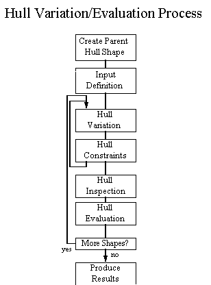
Fig. 1
The overall process flow is shown in the Fig.
1. The program starts with a parent hull and automatically varies
the shape according to the designer's input. Each derivative hull
shape is automatically evaluated, with the results printed,
plotted, or contoured. Each box of the diagram is explained in
the following sections.
The purpose of this program is to show the
feasibility of carefully controlled hull variation for use by
design optimization or evaluation methods. The overall design
optimization is not fully automatic. It is under the control of
the designer who can carefully vary one or two major shape
variables at a time and evaluate the results. By graphing and
contouring these results, the designer can quickly study
tradeoffs for a wide range of hull shapes and progress toward an
optimal design shape.
CREATE PARENT HULL SHAPE
There are many ways to define a hull shape for
use by a computer program. The most common methods are:
o Station definition using offsets
Used for volumetric calculations
o B-spline (NURBS) surface definition
Used for fairing and construction
o Ruling line definition
Used to define developable plates
o Wireframe definition
Station definition plus control lines
o Polyhedron mesh definition
Used for flow and structural calculations
Although all of these hull definition methods
could be applied to the techniques described in this paper, this
example hull variation and evaluation program uses a station
definition of the hull, since a perfectly fair hull surface is
not required for the resistance evaluation.
This example program is part of the New Wave
System's Nautilus System software for ship design and
construction which allows you to create a station definition of a
hull by typing in a table of offsets, by digitizing a body plan,
by reading an existing offset file (SHCP-Ship Hull
Characteristics Program, GHS-General Hydrostatics, etc.), or by
converting a B-spline surface definition to a station definition.
Once a station definition of a hull (parent hull) is created and
stored in the vessel's database, the hull variation and
evaluation program can be started.
INPUT DEFINITION
The program starts by reading the station
definition of the parent hull from the vessel's database. Since
the evaluation method being applied to the hull is a resistance
calculation, the input values must either come from the shape of
the boat or input by the designer. These inputs are listed below.
Basic input from the designer - This
data includes things that are not dependent on the shape of the
boat, such as boat velocity, water type, and drag options.
Input from the shape of the hull - All
hull shape data required by the resistance evaluation program is
obtained during the hull "Inspection" routine,
discussed later in the paper.
Input of the hull variation constraints
- This input tells the program which variables to vary to
maintain the proper hull constraints. The two main constraints
are constant draft (T) and constant displacement (Disp). This is
discussed in the Hull Constraints section.
Input of the calculation and output choices
- This input tells the program whether to perform a single
calculation, a print or plot over a range of values, or a contour
plot over a matrix of input values. The print or plot option
allows the designer to vary one of the major design parameters
while holding the rest of the variables constant. The contour
plot allows the designer to vary two major design variables while
holding the rest constant.
Once all user-defined input variables have been
entered, the program begins its automatic hull variation and
evaluation process.
HULL VARIATION
The process of hull variation produces a
derivative hull from a parent hull by specifying new values for
any of the following major parameters:
1. Length of the waterline (LWL)
2. Beam of the waterline (BWL)
3. Depth of the boat (Depth)
4. Draft (T)
5. Displacement (Disp)
6. Prismatic coefficient (Cp)
7. Longitudinal center of buoyancy (lcb)
8. Parallel middle body - forward (Pfwd)
9. Parallel middle body - aft (Paft)
10. Midship coefficient factor (Cmfact)
Because many of these parameters are
interrelated, the designer must choose whether the calculations
are done for a fixed draft or for a fixed displacement. These
variables fall into one of the following hull variation routines:
Stretch, Balance, Lackenby, or CmVary.
Each of these will be discussed below.
STRETCH
This hull variation routine varies any or all
of the three major dimensions (length, beam, and depth) by a
scale factor. This is a very simple hull variation applied to all
offsets of the station definition.
BALANCE
This step doesn't actually change the shape of
the station definition, but it does modify some of the major
parameters. If the user selects a constant displacement hull
variation constraint, then this routine will raise or sink the
hull to search for a new draft (T) which maintains a constant
displacement. This is done with a searching technique which
maintains zero trim while searching for the desired displacement.
Note that if the draft changes, the LWL and the BWL will likely
change. If a constant draft option is selected, this routine
calculates the new displacement for the current hull shape
LACKENBY
This is a technique for hull variation
developed by H. Lackenby [5] (see also [6]), which allows the
designer to vary any of the following variables, without
affecting the LWL, BWL, and the depth of the vessel.
o Prismatic coefficient (Cp)
o Longitudinal center of buoyancy (lcb)
o Parallel middle body - forward (Pfwd)
o Parallel middle body - aft (Paft)
The Lackenby method is a quadratic variation of
the "one minus prismatic" approach whereby the lengths
of the parallel middle body can be controlled independently of
lcb and the prismatic coefficient. The sectional area curve is
calculated for the boat and the curve is shifted to achieve the
target values. Half-breadths and heights of the offsets in the
station definition are not changed using this method; only the
longitudinal locations of stations are shifted.
It can take a few iterations of this method to
zero in on the desired values. The more stations in the
definition, the more accurate it is and the less iterations it
takes. The program developed for this paper repeats the Lackenby
hull variation calculation until all four variables are within a
small tolerance of the target values.
Although the Lackenby hull variation technique
allows the designer to vary and set any one or all of these
variables, the displacement does change for a constant draft.
An example of this variation can be seen in the
following two figures. Fig. 2 shows a parent sailboat canoe-body
hull shape with a prismatic coefficient of 0.534. Fig. 3 shows a
derivative hull with a target prismatic coefficient of 0.60. Note
that although the overall length may vary, the waterline length
is fixed and the lcb position is fixed.

Fig 2. Sailboat Hull With
a Prismatic Coefficient of 0.534

Fig 3. Sailboat Hull With
a Prismatic Coefficient of 0.60
This example of the Lackenby approach was
applied to a B-spline surface model of the sailboat to be able to
show the smooth transition of buttock shapes. The hull variation
program used for this paper, however, applies the same technique
to a station definition of a hull.
CMVARY
This is a hull variation technique, developed
by the author, that allows the midship shape of the vessel to
change independently of the beam and depth of each station. It
uses a value called Cmfact which varies the shape of each section
diagonally in the direction of the bilge corner, defined as the
intersection of the maximum beam and depth of the station. A
Cmfact value of 1.0 means that each section shape is rectangular.
(See Fig. 4)
Cmfact is related to the midship coefficient
(Cm) of a vessel, except that it is based on the overall maximum
beam and depth of the vessel, rather than the waterline beam and
the draft. Since all of these hull variations affect the entire
hull shape, a Cm-type factor was created that also affects the
entire section, rather than just the area below the waterline.
This makes the factor independent of the draft and displacement.
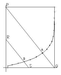
Fig 4. Station showing
Cmfact diagonal
The Cmfact value for a particular station is
the percent distance of the station curve from point P (0.0)
towards point Q (1.0). The overall Cmfact for the hull is the
largest Cmfact of all of the stations and is the value used by
the CmVary routine to vary the shape of the hull.
CmVary Hull Variation Steps
1. Find the section with the largest Cmfact
value. This is the one Cmfact value that is used for the entire
boat.
2. Given a new, target Cmfact, determine the
percent increase or decrease of the defining Cmfact section along
the diagonal (P-Q) variation line.
3. Decrease this Cmfact change percentage
parabolically to zero at each end of the boat. This means that
this hull variation tapers off to zero change at the ends of the
boat.
4. Apply the appropriately decreased Cmfact
change percentage to each station. For each offset point (B),
construct a line (R-S) parallel to the main station diagonal
(P-Q) and determine the intersections with the defining
beam-depth station box (points R and S). Stretch or shrink each
offset point along this line by the appropriate Cmfact change
factor. Point B is moved towards (or away from) point S by the
same percentage as point A is moved towards (or away from) point
Q. As the global value of Cmfact approaches 1.0, the shape of
each section approaches the rectangular shape of the defining
beam-depth box.
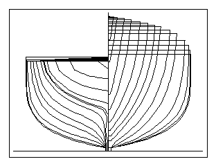
Fig 5. Parent hull shape
with a Cmfact of 0.76
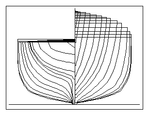
Fig 6. Derivative hull
shape with a Cmfact of 0.80
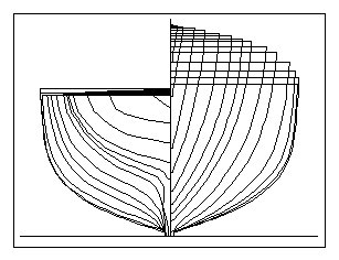
Fig 7. Derivative hull shape with a Cmfact of 0.72
Figs. 5, 6, and 7 show the parent and two
derivative hulls with larger and smaller values of Cmfact. Fig 5
shows the parent hull with a Cmfact of 0.76, Fig. 6 shows a
derivative hull with a Cmfact of 0.80, and Fig. 7 shows another
derivative hull with a Cmfact of 0.72.
There were difficulties with large changes in
the Cmfact value due to its linear transformation of each station
toward either of its two diagonal corners. As the change got
larger, each section shape developed a corner knuckle or dimple,
depending on the direction of variation from the parent shape.
Rounding off the hard knuckle corner (at point Q) to use for a
Cmfact value of 1 would improve this problem. It would give the
vessel a small bilge radius for a Cmfact of 1.0, and would smooth
the section shape changes over a greater range of Cmfact values.
OTHER VARIATIONS
There are many more potential avenues for hull
variation, such as:
o Variation of the deadrise angle
o Variation of the profile rocker of the boat
o Change sections from U-shapes to V-shapes
o Change section shapes while
maintaining constant LWL, BWL, draft, and section area.
Many of these hull variations are important in
their own right, but for the resistance evaluation routine
described in this program, they play a smaller role than varying
the major hull shape parameters.
HULL CONSTRAINTS
The Stretch variation changes the
length, beam, and depth of the boat, but the displacement, Cp,
lcb, etc. all change. Balance determines the new draft (T)
for a given displacement, but the length, beam, Cp, etc. all
change. Lackenby maintains constant LWL, BWL, and draft,
while varying Cp, lcb, Pfwd, and Paft, but displacement changes. CmVary
maintains constant length, beam, and draft, but varies the
displacement and prismatic coefficient. It is impossible to fix
all of these major design variables to create one specific
derivative hull shape. If one variable is set or changed by the
program, then at least one other variable must change at the same
time. The goal, however, is to allow the designer to change the
major design variables in a controlled manner using constraints.
The following equations show the relationships
among many of the major design variables.
![]()
![]()
![]()
![]()
![]()
where sa(x) is the sectional
area at x
In an ideal case, the designer should be able
to vary any parameter in the above equation and to select any
other parameter to balance the equation so that the rest of the
parameters remain fixed. This may be possible, but it might
require a whole range of constraint maintenance routines. The
program described in this paper only allows the designer to vary
either the draft or the displacement to obtain target values of
the major design parameters. For example, a designer might vary
LWL, while maintaining fixed values for the rest of the
parameters, except for draft, which would have to vary to
maintain constant displacement.
Another way of looking at the problem is to fix
all parameter values but one, and then solve (search) for a
derivative hull that meets those set values. That is what the
program in this paper does. Specifically, this program can
generate a derivative hull shape with any values for the major
variables, except for displacement and draft. If the draft
constraint is set by the designer, the program will vary
displacement to achieve all of the other target values. If the
displacement constraint is set, the draft of vessel changes while
achieving the rest of the target variables. This hull variation
and constraint search loop is shown in Fig. 8.
Given target values for length, beam, depth,
Cp, lcb, Pfwd, Paft, and Cmfact, this search loop will vary
either draft or displacement to create a derivative hull with the
desired values. This non-linear Hull Variation and Constraint
search loop has gone through many variations to speed up the
search process. It uses a form of a conjugate direction search
technique to zero in on a solution. The balance step is performed
after each hull variation step, since all parameters are very
sensitive to draft and displacement.
This is just one approach to the constraint
maintenance problem. One could derive a hull variation and
constraint search loop based on varying any of the major design
variables. Note that a new search technique would be needed by
this program if both the displacement and the draft of the vessel
are to be fixed. One could easily achieve this, however, by
varying BWL, for example.
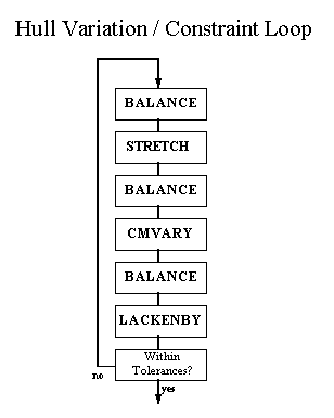
Fig. 8
There are also limits to the range of parameter
values that can be achieved. Some shapes are physically not
possible, but then again, those shapes are of no interest to the
designer.
HULL INSPECTION ROUTINE
Once the hull variation and search loop is
complete, this routine determines all of the hull shape
information that is required by the Hull Evaluation routine.
Exactly what is calculated here depends on the needs and
sophistication of the evaluation routine. For many resistance
calculation programs, this might mean calculating simple
information, such as volume, wetted surface, waterplane area, and
the half angle of the waterplane entry. Most of these values are
determined automatically from the hydrostatic calculations in the
Balance routine.
In addition, this inspection routine can also
calculate the righting moments and righting arm areas of the
vessel for any heel angle, with automatic balancing for trim.
This allows the designer to study the trade-offs between
resistance and stability.
HULL EVALUATION ROUTINE
In discussing the automatic hull variation and
optimization process, little was said about the specific type of
evaluation routine that would be used to analyze the shape of the
hull. For this paper, a resistance technique based on the use of
a "Geosim" coefficient approach is used. This technique
estimates the overall resistance of a vessel by splitting the
resistance into component parts, such as viscous resistance,
residual resistance, and appendage resistance.
In general, however, this hull variation and
constraint technique can be used with any hull shape evaluation
technique. A sample of the major evaluation categories are given
below. Following that is a more detailed description of the
Geosim technique used in this program.
1. Geosim Coefficient Resistance Evaluation
- These techniques break the overall resistance of the vessel
into their component parts, such as viscous resistance (Cv),
residual resistance (Cr), and appendage resistance. Residual
resistances are often determined from a regression analysis of
tank test data.
2. Planing Hull Resistance - This type
of resistance calculation uses the same force breakdown
techniques as the Geosim approach, but adds the moments of forces
about the center of gravity of the boat. This defines a steady
state free body diagram of the boat that can be solved for the
resistance and trim of the boat.
3. Sailboat Velocity Prediction (VPP)
-This type of resistance prediction is also based on a Geosim
approach, but adds sail and hull lift and drag forces. A search
technique is used to determine the velocity and heel angle of the
boat for each wind speed and wind angle.
Note that for certain racing sailboats, the
hull variation process is further complicated by the need to meet
the shape constraints of any applicable rule, such as the
America's Cup rule.
4. Computational Fluid Dynamics Methods
(CFD) - These techniques typically use a polyhedron mesh
generated from the shape of the hull to perform a full 3D
analysis of the resistance of the hull.
5. Finite Analysis Methods (FEM) - These
techniques use a polyhedron mesh generated from the shape of the
hull to perform a 3D structural finite element analysis of the
hull shell.
Geosim Coefficient Resistance Evaluation
The program described in this paper uses a
Geosim approach to the evaluation of the vessel's resistance.
This technique breaks the overall resistance into the following
resistance components:
o Total Resistance (Rtot)
![]()
o Viscous Resistance (Rvisc)
![]()
![]()
Cf - Based on ATTC or ITTC57 friction lines
k - 3D viscous form factor
o Residual Resistance (Rresid)
![]()
o Correlation Allowance Resistance (Rcorr)
o Appendage Resistance (Rapp)
o Bulb Resistance (Rbulb)
o Transom Resistance (Rtrans)
o Air Resistance (Rair)
The program contains several different choices
for each of the categories of resistance described above. The
designer either selects an overall resistance approach from a
menu or creates a customized approach by selecting one technique
from each of the resistance categories.
Most of the results in this paper come from
applying the Holtrop [14],[15] ship resistance methods for each
of the resistance components.
The details of these calculations are not
presented here, since the goal of this paper is to describe the
overall hull variation, constraint, and evaluation process,
rather than the particular resistance calculation methods used.
PRODUCTION OF RESULTS
The designer determines whether one condition
is calculated and printed, a looping print is produced, a looping
plot is produced, or a contour plot is produced. Each of these
choices is described below. First, input and output variables and
algebraic expressions will be briefly discussed.
Program Variables
All program input, intermediate, and final
calculation variables are defined and labeled for access by the
designer. Input variables are also broken into two categories:
hull shape independent and hull shape dependent variables. Hull
shape dependent input variables include LWL, BWL, Depth, T, Disp,
Cp, lcb, Pfwd, Paft, and Cmfact. Hull shape independent variables
include values such as boat velocity, water type and temperature,
and vertical center of gravity (VCG).
Most intermediate and all final calculation
values are also labeled for use by the designer. This is useful
if there is a need to study the details of the resistance
calculation technique itself. If some of the results seem
questionable, the designer may evaluate all of the individual
variables of the resistance calculation to see if some result
values are abnormal. This is important for both program
verification and resistance model validation. No calculation
program should present itself to the designer as a "black
box" evaluation.
Algebraic Expressions
For any of the output choices, the designer can
also specify any algebraic combination of input and output
variables to display or print. The program will parse the
expression after the resistance calculation is done and evaluate
the expression using the proper variables. For example, a
designer might vary LWL over a range of values using a constant
draft constraint and request that the program print the value for
the expression (Rtot/Disp) as one of its output variables. In
addition, all algebraic and trigonometric functions, such as
SQRT, LOG, and TAN, can also be used.
Single Calculation
The designer selects the target values of all
major hull shape parameters, along with a required constraint:
constant draft or constant displacement. Input also consists of
non-hull shape information, such as boat velocity, water type and
temperature, and vertical center of gravity.
The calculation section first searches for the
single target hull shape, then calculates the resistance
information, and finally displays or prints all input,
intermediate, and final results.
Looping Print Calculation
The user specifies any single input variable
and the range of values it will take. The program automatically
performs a complete hull variation for each value of the input
variable, calculates the results, and displays or prints the
designer-selected input and output variables and expressions.
The following output shows the results for
varying BWL from 80 to 120 feet, with constant displacement and
variable draft. Note that the other major design parameters are
held constant, to within a one-half percent search tolerance.
BWL LWL Disp Cp LCB Rtot
80.02 307.51 15142 0.6794 0.0408 53.01
85.02 307.01 15147 0.6796 0.0409 51.51
90.02 306.56 15153 0.6797 0.0416 50.05
95.01 306.40 15158 0.6799 0.0402 48.82
99.97 305.79 15162 0.6801 0.0413 47.83
104.92 305.48 15162 0.6799 0.0415 47.17
109.88 305.08 15159 0.6799 0.0419 46.81
114.74 304.73 15159 0.6799 0.0419 46.74
119.93 305.76 15157
0.6799 0.0425 47.02
BWL T LWL/BWL LWL/T Rvisc Rresid
80.02 41.09 3.84 7.48 35.73 14.99
85.02 39.26 3.61 7.81 36.10 13.11
90.02 37.62 3.40 8.14 36.57 11.16
95.01 36.11 3.22 8.48 37.16 9.32
99.97 34.78 3.05 8.79 37.79 7.67
104.92 33.56 2.91 9.10 38.56 6.22
109.88 32.43 2.77 9.40 39.39 4.98
114.74 31.39 2.65 9.70 40.30 3.96
119.93 30.27 2.54 10.09 41.42 3.09
Also note that the purpose of this paper is to
demonstrate the hull variation, constraint and evaluation
techniques, and not to evaluate the actual numbers produced by
the resistance part of the program.
Looping Plot Calculation
This function works the same as the Looping
Print Calculation, except that the results are plotted. In this
case, however, the designer specifies the independent input
variable to vary and the data to be plotted.
The plotted data consists of one or more
ordinate variables or expressions and one abscissa variable or
expression. Note that the abscissa variable does not have to be
the same as the independent input variable. The designer can plot
any variable or expression versus any other variable or
expression. This can be done for any input, intermediate, and
final result variables. The designer can also specify the title,
labels, tick marks, and grid options of the graph.
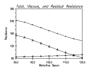
Plus - Total Resistance
Circle - Viscous Resistance
Triangle - Residual
Resistance
Fig. 9 Example of the
Looping Plot Output
Contour Plot Calculation
The contour plot function allows the designer
to plot contour graphs of variables or expressions over a range
of two input variables. For example, constant contour lines of
Rtot can be plotted over a range of LWL and BWL values, using a
constant displacement constraint. The program will vary the hull
shape over a matrix of LWL and BWL values while maintaining
constant values for the rest of the major design parameters
(except for draft, which must vary to achieve a constant
displacement).
Like the Looping Plot Calculation, this
function allows you to specify multiple contour variables or
expressions to be plotted at one time. The abscissa and ordinate
values or expressions also do not have to be the same as the
independent variables.
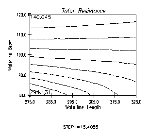
Fig. 10 Example of the
Contour Plot Output
This graph shows constant resistance contour
lines over a range of LWL and BWL values. This is drawn like a
topographical map of total resistance, with the lowest and
highest points of resistance identified and labeled (in tons of
resistance). The lowest total resistance is located at the
shortest length and the widest beam. Note that the draft is also
less at this point because of the constant displacement
constraint. Graphs like this might raise more questions about the
resistance calculation than they answer, but that is preferable
to using a resistance calculation program like a black box
calculator. The designer can explore other variations in shape
and compare the results with the equations used by the resistance
model. In addition, this hull variation and evaluation approach
can be invaluable to those developing new resistance techniques
based on regression analysis techniques.
CONCLUSIONS
The computer program described in this paper
demonstrates the ability to automatically vary the shape of a
parent hull to obtain target values for the following major hull
shape variables: LWL, BWL, depth, draft, displacement, Cp, lcb,
parallel middle body-forward (Pfwd), parallel middle body-aft
(Paft), and Cmfact. Target values are achieved using a constant
displacement or constant draft constraint. If a constant draft
constraint is selected, then all of the target values are
obtained by varying the displacement of the vessel. If a constant
displacement constraint is selected, then the target values are
obtained by varying the draft of the vessel.
The program also demonstrates the process of
automatically varying a parent hull shape over a range of target
values, evaluating the hull shape using a "Geosim"
resistance calculation routine, and printing, plotting, or
contouring the results.
FUTURE WORK
This paper only scratches the surface in the
area of automatic hull variation with constraints. As mentioned
previously, the designer should be able to achieve the desired
target values for all major design variables by varying just one
selected parameter. In this paper, this was achieved by varying
the draft or displacement. It should be a straight-forward
change, however, to vary another variable, such as LWL, to
achieve the desired target values.
There are also an infinite variety of other
hull variations to investigate, such as variable bilge radius,
variable deadrise angle, adjustable rocker shape, and adjustable
section shape. This paper focused on variations of the major
design parameters, since those variables had the greatest
influence on the resistance calculation technique.
An associated area of development is the
automatic creation of hull shapes from a set of standard form
parameters. One could automatically create an approximate hull
shape from form parameters and use the automatic hull variation
process to achieve the exact target values.
Another area of development is to separate the
hull variation routine, the hull inspection routine, the hull
evaluation routine, and the output results routine into separate
modules or programs, linked by a simple data and geometry file.
This would allow designers to replace the existing evaluation
routine or program with their own, but still use the standard
hull variation and results evaluation framework.
Other versions of this program are under
development; one for the planing boat model and another for the
Velocity Prediction Program (VPP) model for sailboats. Each of
these hull types have their own special hull variation and
constraint requirements.
Another interesting area of development is in
the automatic variation of CFD or FEM hull meshes. Rather than
remeshing after each hull variation (which may not be automatic),
the hull variation could be performed directly on a parent hull
mesh. This would eliminate the need for remeshing after each step
and would allow the analysis program to analyze many hull
variations without human intervention.
REFERENCES
1. Todd, F., "Series 60, Methodized Experiments with Models of Single-Screw Merchant Ships" DTMB Report 1712, July, 1963
2. Gertler, M., "A Reanalysis of the Original Test Data for the Taylor Standard Series", DTMB Report 806, March, 1954
3. Moor, D., Parker, M., and Pattulo, R., "The BSRA Methodical Series - An Overall Presentation", Trans. RINA, vol 103, 1961
4. Lap, A., "Diagrams for Determining the Resistance of Single Screw Ships", International Shipbuilding Progress, vol 1, no. 4, 1954
5. Lackenby, H., "On the Systematic Geometrical Variation of Ship Forms", Trans. INA, Vol 92, 1950, pp 289-315
6. Botting, M., "Hull Form Derived From Parent", DTMB Report 2328, Feb, 1967
7. Volker, H., "Systematic Variation of Usual Ship Form", International Shipbuilding Progress, vol 1, no. 1, 1954
8. Reed, A. and Nowacki, H., "Interactive Creation of Fair Ship Lines", Journal of Ship Research, vol 18, 1974, pp 96-112
9. Kuiper, G. "Preliminary Design of Ship Lines by Mathematical Methods", Journal of Ship Research, vol 14, 1970, pp 52-66
10. Nowacki, H., Creutz, G., and Munchmeyer, F., "Ship Lines Creation by Computer - Objectives, Methods and Results", First International Symposium on Computer-Aided Hull Surface Definition (SCAHD77), pp 1-18, SNAME, Anapolis, MD, 1977
11. Soding, H. and Rabien, U., "Hull Surface Design by Modifying an Existing Hull", First International Symposium on Computer-Aided Hull Surface Definition (SCAHD77), pp 19-29, SNAME, Anapolis, MD, 1977
12. Nowacki, H. and Reese, D., "Design and Fairing of Ship Surfaces", Surfaces in Computer Aided Geometric Design, North Holland, Eds. Barnhill, R. and Boehm, W., 1983, pp 121-134
13. Standerski, N., "The Generation of Ship Hulls With Given Design Parameters Using Tensor Product Surfaces", Theory and Practice of Geometric Modeling, Eds. Strasser, W. and Seidel, H., Springer Verlag, 1989, pp 65-79
14. Holtrop, J. and Mennen, G., "An Approximate Power Prediction Method", International Shipbuilding Progress, Vol 29, July, 1982
15. Holtrop, J. "A Statistical Re-Analysis
of Resistance and Propulsion Data", International
Shipbuilding Progress, Vol 31, Nov, 1984