A curve entity for ProBasic and ProSurf defines a connected series of points in space. This entity type includes lines, polylines, NURB curves, and combo curves, which are combinations of lines, polylines,
and NURB curves. This entity type can be used for a variety of purposes where there is no need for full surface definitions. One example is to use these entities in profile view to construct a 2D sail plan for a 3D surface definition of the hull and deck. Keep in mind that the end product of a design is not always a full 3D surface model of a boat. Another use of these entities is to define key curves and lines of a hull in its very early design phase. Later, surfaces can be constructed to fit the previously-defined curve entities. For ProSurf, curve entities can be attached to surfaces to define trimmed sections or to define longitudinal stringer trace lines. Although entities of this sort are always found in CAD programs, you may find it much easier to perform certain tasks in ProBasic/ProSurf and then transfer the resultant geometry to the CAD program.
The very unique aspect of this entity is that it covers both polylines and NURB curves in one entity type, which makes it extremely easy to adapt to a variety of curve and line design problems.
The following section discusses the process of defining, modifying, and deleting curve entities.
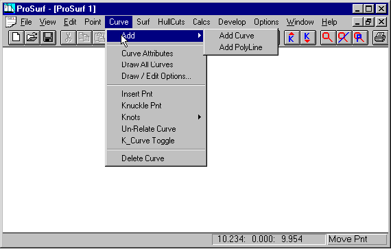
This first screen for the curve entity type shows the main set of commands for creating and manipulating these entities. In particular, it shows the sub-menu listing the two methods for defining this type of entity. As you will see, this entity starts off as a polyline or a NURB curve, but can be easily changed back and forth and be converted to a combination polyline/NURB curve.
The next screen shows and discusses how these entities are created.
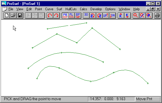
This screen shows several examples of both polylines and NURB curves. They were created as follows:
1. Select either the Add Curve or the Add Polyline command. Notice that the command becomes the current command and the proper label appears in the lower right.
2. To enter a polyline or a curve, "click" the left mouse button for each point along the entity. You will notice that the program dynamically shows you the shape of the entity as you are creating it.
3. After you "click"-enter the last point of the entity, terminate the entity by pressing the right mouse button. The position of the cursor when you press the right mouse button is not added to the entity.
4. If only two points are entered for a polyline or a NURB curve, the entity defaults to a simple line.
5. You can continue to enter polylines or NURB curves as long as the associated command label appears in the lower right. (It will change if you select a different command.)
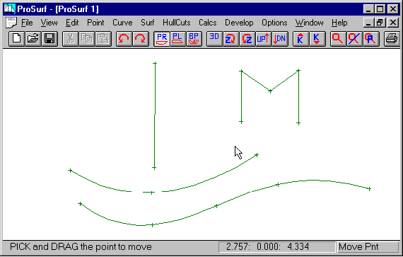
This screen shows the results of moving various points which define each of the entities. To do this, you need to first select the "Move Point" command under the "Edit" set of pull-down commands. You can then move as many points as you wish without re-selecting the "Move Point" command, as follows:
1. Select the "Move Point" command under the "Edit" set of pull-down commands.
2. Position the cursor near the point you wish to move. (Actually, the Move Point command works for any point on any entity type: point, curve, polyline, and surface.)
3. Press down and hold the left mouse button.
4. While holding down the left mouse button, "drag" the point to a new position.
5. When the point is placed in its new position, release the left mouse button.
6. The polyline or NURB curve will dynamically change to reflect the new point position.
You can continue this Move Point process until you select another command. Always look in the lower right corner to see the current command.
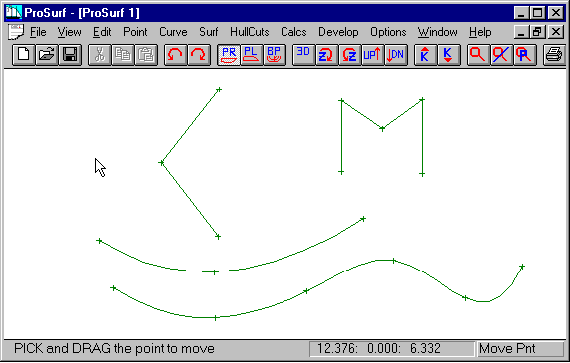
This screen shows the results of inserting points into two of the entities: one polyline and one NURB curve. Inserting points into this entity type is done with the "Insert Pnt" command in the Curve pull-down menu. The process is as follows:
1. Select the "Insert Pnt" command in the "Curve" pull-down menu. Notice that the command becomes the current command and the proper label appears in the lower right.
2. Position the cursor anywhere along any of the polyline or curve entities.
3. "Click" the left mouse button to insert the point. If you are not "close enough" to the entity, the program will tell you to re-position the cursor and try again.
4. If you are close enough (you actually do not have to be very close), the program will erase and redraw the entity showing an edit ('+') mark at the new position.
5. You can continue this insertion process as long as the insert command remain current.
NOTICE: The points are inserted without affecting the position of the other points that define the entity, although the shape of a NURB curve may change slightly. The screen above shows the results of inserting two points and the results of moving those two points.
One thing not discussed here is the deletion of polyline/curve points. This is done with the "Delete Pnt" command under the Point set of pull-down commands. One might reasonable expect that this command would work for only point entities, but actually, it works for both point and curve entity types. We thought about including a delete point command just for curve entities, but decided to stick with the one "Delete Pnt" command.
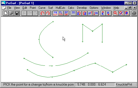
So far, you have seen how to create, modify, and insert into polylines and curves. To see how polylines and curves are variations of the same entity type, you need to use the "Knuckle Pnt" toggle command in the Curve set of pull-down menus. As shown in the screen above, the two points which were previously inserted into the entities have been converted from knuckle point to "smooth" point (or vice-versa). A "knuckle" point is a point along a curve (or polyline) which makes a hard turn. This knuckle point "toggle" command allows you to pick any interior polyline or curve point and convert it from smooth to knuckle point or from knuckle point to smooth point. If the point is smooth, it will convert it to a knuckle point. If the point is a knuckle point, this command will convert it to a smooth point. The process works as follows:
1. Select the "Knuckle Pnt" command from the "Curve" set of pull-down menus. Notice that the command becomes the current command and the proper label appears in the lower right.
2. Position the cursor near the point you wish to convert (toggle) and "click" the left mouse button. The entity will be immediately redrawn with the converted curve shape.
3. You can repeat this command immediately for any other curve/polyline interior point.
As you can see, this command allows you to convert a polyline to a curve (or vice-versa) very quickly. Many logical design entities are combinations of polylines and curves. You would start by entering a rough polyline shape and then use the Knuckle Pnt command to refine the polyline shape with the appropriate curve sections. Most all general-purpose CAD programs do not allow you to combine polyline and curve entities together as one entity. They force you to create them separately and to join them as required - a tedious process. Our entity type allows you to quickly toggle between the polyline and curve shapes, or some combination of each.
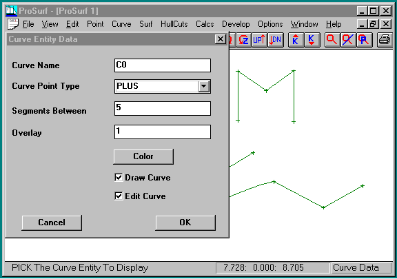
All geometric entities have properties or attributes associated with them, such as point type and entity color. This screen shows an attribute dialog box for one particular curve entity. It was displayed as follows:
1. Pull down the Curve set of commands and select the "Curve Attributes" command. Nothing will happen except that this becomes the "current" command and the label "Curve Data" is displayed in the lower right corner of the window.
2. Move the cursor near one of the curve entities and "click" the left mouse button (anywhere along the curve).
3. A dialog box, like the one shown above, will appear..
4. The attribute fields are:
Curve Name - The curve's name, created by the program. You can change it, if you wish.
Curve Point Type - The type of symbol to use to mark the curve point's position.
Segments Between - The number of straight line segments used to display the curve between each set of defining points.
Overlay - The overlay layer of the entity. (Currently not used by the program)
Color - Color to use for the curve.
Draw Curve - Option to turn off the display of the entity. Use the Draw All Curves command to turn on the display of the curve.
Edit Curve - This allows you to display the curve, but to disable the ability to change its position.